Introduction
Let’s face it: nowadays, most musical performances are complimented by some fancy light shows. Go to any concert, festival, club – they all have a corresponding visual performance or effects. Why not add your own home to that list? Here’s a simple yet effective project to make your very own son et lumière!
Required Materials
To follow along with this tutorial, you’ll need the following materials. The partial wishlist on the left is for the simple circuit. It does not include the potentiometer and buttons. The full wishlist on the right is for the full circut. You may not need everything though depending on what you have. Add it to your cart, read through the guide, and adjust the cart as necessary.
Any microcontroller with 3.3V and 5V pins will suffice. Any analog potentiometer and size momentary button should work. Depending on your intent, the trimpot and buttons may not be necessary.
- Trimpot – The trimpot is only used to adjust the brightness threshold, so, if you want maximum brightness, you don’t have to worry about incorporating it.
- Buttons – The three buttons cycle visualizations, color schemes, and shuffle mode respectively, so, if you want to do without those features (and just use shuffle mode all the time), that’s also a possibility.
If you’re compiling from the Arduino IDE or similar, you’ll want to snag the the NeoPixel Library since the code used is heavily based on it. The resistor and capacitor are not required, but they will help prevent possible damage to the LEDs. Any resistor between 300–500 Ω can be used.
It is also suggested that you use an Arduino and Breadboard Holder to simplify wiring and to mount the LED strip:
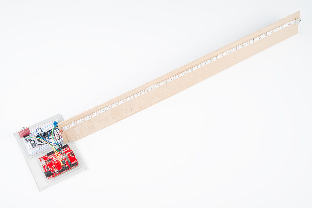
A small notch was cut in the Breadboard Holder to hold a piece of MDF, on which the LEDs are attached.
Recommended Reading
Before embarking upon this tutorial, you may find the following links useful:
- Arduino.cc
- How to Use a Breadboard
- Wikipedia: RGB Color Model
- WS2812 Breakout Hookup Guide
- Sound Detector Hookup Guide
- How to Power a Project
Since we’re using the NeoPixel library, it may also be a good idea to get familiar with the NeoPixel Documentation.
Assembly
Depending on your setup, the project may not require any soldering! The few exceptions will probably be soldering some pins to the sound detector, and, if you’ve cut a roll of addressable LEDs in the middle, you’ll have to solder some wires to the starting LED’s pins. If you’ve never soldered before, I highly suggest taking a look at this guide to solder.
Below is also a general chart for how the pin(s) on each component should be routed and an accompanying diagram. Before you begin, here are some things to keep in mind:
- Be conscious of the orientation you think would allow the sound detector to take optimal readings for your intentions. Bending the pins to hold the sound detector perpendicular to the breadboard is a recommended option.
- Electrolytic capacitors are polarized, so how they are oriented is important. Make sure to place the side with a white stripe and a negative symbol into a negative current (ground) and the other into positive current.
- Resistors and pushbuttons are not polarized.
- Trimpots are not polarized either, however their middle pin is the analog output, so don’t power that directly.
The pins used in the diagram and the code are in parentheses. If you use a different pin, don’t forget to change it in the code as well:
| Sound Detector | Addressable LED strip | Trimpot | Pushbutton | 1 mF (1000 µF) Capacitor | 300–500 Ω Resistor |
|---|---|---|---|---|---|
| Envelope → Analog (A0) | Digital/Analog (A5) → Resistor → DIN | 5V → left or right pin | GND → Either side | Between ground and 5V | Between Digital/Analog (A5) and DIN on LED strip |
| 3.3V → VCC | 5V →5V | Middle pin → Analog (A1) | Other side → Digital (4, 5, 6) | ||
| GND → GND | Remaining left or right pin → GND |
The circuit should look something like the diagrams below. If you just want the LEDs to react to sound using one visualizer and one color palette, you can build the simple circuit on the left. If you want to take advantage of all the visuals, palettes, and shuffle mode, you can build the full circuit on the right.
 |
 |
| Simple Circuit | Full Circuit |
Fritzing diagram for the circuit as described above. Click the images for a closer look.
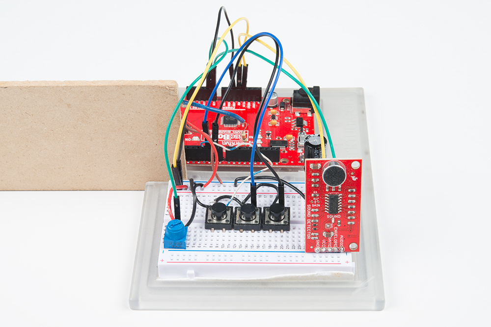
After assembling the circuit, you should have something similar to the image below. Depending on your setup, you may have less components.