Step 1: Parts List
Step 2: Schematics
Refer to opening video’s assembly section and schematic below to see how to place parts on a PCB.
Use schematic provided above for correct wiring.
Step 3: Design and 3D Print the Case
After we have measured the parts, it is time to design a 3D case and print it!
Design
Here is the link to my design: https://www.tinkercad.com/things/dG47Pr28uwx
Case above is designed to perfectly fit all the components listed above.
Front part will hold the LCD screen and color sensor.
Main 3×7 cm PCB will hold DFRDuino Pro Mini, battery holders and 3 push buttons and will be screwed on the back part from inside.
RGB LED will sit inside the top section of the back part.
Power switch will fit in the small hole on the back part.
Printing
3D models ready for printing are available on Thingiverse: https://www.thingiverse.com/thing:3223709
Print settings may vary depending on your printer.
Supports are needed for battery cover part and front part because front part has a built in distancer to provide distance between color sensor and specimen.
Assembly
For assembly instructions please refer to the assembly section of the video provided at the beginning.
Step 4: Source Code
You are more than welcome to improve the code, as the code provided is only the starting point, but works well.
This project uses these 2 specific libraries, so make sure you add these to your Arduino IDE:
#include <DFRobot_TCS34725.h>
#include <DFRobot_LCD.h>
#define ledPin 12
#define redpin 3
#define greenpin 5
#define bluepin 6
const int8_t button1Pin = 7; //1
const int8_t button2Pin = 8; //2
const int8_t button3Pin = 9; //3
int8_t button1State = 0;
int8_t button2State = 0;
int8_t button3State = 0;
#define ACTIVATED LOW
// for a common anode LED, connect the common pin to +5V
// for common cathode, connect the common to ground
// set to false if using a common cathode LED
#define commonAnode true
// our RGB -> eye-recognized gamma color
byte gammatable[256];
DFRobot_LCD lcd(16,2);
DFRobot_TCS34725 tcs = DFRobot_TCS34725(0x50, TCS34725_GAIN_60X);
bool ledEnabled=false;
int lightsMode=0;
// make some custom characters:
byte light_on[8] = {
   0b00100,
   0b00100,
   0b01110,
   0b11111,
   0b11111,
   0b01110,
   0b00000,
   0b10101
};
byte light_off[8] = {
   0b00100,
   0b00100,
   0b01110,
   0b10001,
   0b10001,
   0b01110,
   0b00000,
   0b00000
};
byte rgb_on[8] = {
   0b00000,
   0b10101,
   0b00000,
   0b01110,
   0b01110,
   0b01110,
   0b11111,
   0b11111
};
byte rgb_off[8] = {
   0b00000,
   0b00000,
   0b00000,
   0b01110,
   0b01010,
   0b01010,
   0b10001,
   0b11111
};
void setup() {
 lcd.init();
 // create a new character
 lcd.customSymbol(0, light_on);
 lcd.customSymbol(1, light_off);
 lcd.customSymbol(2, rgb_on);
 lcd.customSymbol(3, rgb_off);
 pinMode(ledPin, OUTPUT);
 digitalWrite(ledPin, LOW);
 pinMode(button1Pin, INPUT);
 pinMode(button2Pin, INPUT);
 pinMode(button3Pin, INPUT);
 digitalWrite(button1Pin, HIGH);
 digitalWrite(button2Pin, HIGH);
 digitalWrite(button3Pin, HIGH);
 pinMode(redpin, OUTPUT);
 pinMode(greenpin, OUTPUT);
 pinMode(bluepin, OUTPUT);
 analogWrite(redpin,0);
 analogWrite(greenpin,0);
 analogWrite(bluepin,0);
 // thanks PhilB for this gamma table! it helps convert RGB colors to what humans see
 for (int i=0; i<256; i++) {
   float x = i;
   x /= 255;
   x = pow(x, 2.5);
   x *= 255;
   if (commonAnode) {
     gammatable[i] = 255 - x;
   } else {
     gammatable[i] = x;
   }
 }
}
void loop() {
 button1State = digitalRead(button1Pin);
 button2State = digitalRead(button2Pin);
 button3State = digitalRead(button3Pin);
 int btn=0;
 if(button1State==LOW){
   btn=1;
 }
 if(button2State==LOW){
   btn=2;
 }
 if(button3State==LOW){
   btn=3;
   lightsMode++;
   if(lightsMode==4){
     lightsMode=0;
   }
 }
 uint16_t clear, red, green, blue;
 tcs.getRGBC(&red, &green, &blue, &clear);
 // Figure out some basic hex code for visualization
 uint32_t sum = clear;
 float r, g, b;
 r = red; r /= sum;
 g = green; g /= sum;
 b = blue; b /= sum;
 r *= 255; g *= 255; b *= 255;
 String redHex,greenHex,blueHex;
 redHex =  String((int)r, HEX);
 greenHex =  String((int)g, HEX);
 blueHex =  String((int)b, HEX);
 lcd.setRGB(r,g,b); //Set lcd backlight RGB Value
 lcd.setCursor(0,0); // print values on lcd
 lcd.print("#"); lcd.print(redHex); lcd.print(greenHex); lcd.print(blueHex); lcd.print("   ");
 lcd.setCursor(0,1);
 lcd.print("rgb(");
 lcd.print((int)r); lcd.print(",");
 lcd.print((int)g); lcd.print(",");
 lcd.print((int)b); lcd.print(")       ");
 if(lightsMode==0){
   ledEnabled=false;
   lcd.setCursor(15,0);
   lcd.write((unsigned char)1);//light off
   lcd.setCursor(14,0);
   lcd.write((unsigned char)2);//rgb led on
   //Set the color of RGB led indicator
   analogWrite(redpin, round(gammatable[(int)r]/4));
   analogWrite(greenpin, round(gammatable[(int)g]/4));
   analogWrite(bluepin, round(gammatable[(int)b]/4));
 }
 if(lightsMode==1){
   ledEnabled=true;
   lcd.setCursor(15,0);
   lcd.write((unsigned char)0);//light on
   lcd.setCursor(14,0);
   lcd.write((unsigned char)2);//rgb led on
   //Set the color of RGB led indicator
   analogWrite(redpin, round(gammatable[(int)r]/4));
   analogWrite(greenpin, round(gammatable[(int)g]/4));
   analogWrite(bluepin, round(gammatable[(int)b]/4));
 }
 if(lightsMode==2){
   ledEnabled=true;
   lcd.setCursor(15,0);
   lcd.write((unsigned char)0);//light on
   lcd.setCursor(14,0);
   lcd.write((unsigned char)3);//rgb led off
   //Set the color of RGB led indicator
   analogWrite(redpin, 255);
   analogWrite(greenpin, 255);
   analogWrite(bluepin, 255);
 }
 if(lightsMode==3){
   ledEnabled=false;
   lcd.setCursor(15,0);
   lcd.write((unsigned char)1);//light off
   lcd.setCursor(14,0);
   lcd.write((unsigned char)3);//rgb led off
   //Set the color of RGB led indicator
   analogWrite(redpin, 255);
   analogWrite(greenpin, 255);
   analogWrite(bluepin, 255);
 }
 if(ledEnabled){
   digitalWrite(ledPin, HIGH);
 }else{
   digitalWrite(ledPin, LOW);
 }
 //delay(10);
}
Step 5: Enjoy Your New Tool + Improvement Plans
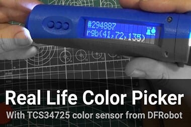
Now you can go around and pick some nice colors 🙂
Currently only the 3rd button is used to cycle through lights as shown in video.
Plan for near future is to implement functionality for other buttons:
button 2 will bring up menu, containing color picker history and much more!
if in menu mode button 1 acts as select, button 3 will act as back/escape
button 1 should pick a color and store it in memory s oyou can cycle through last 10 colors
I hope you enjoyed this tutorial and will have fun using this color picker!
Schematics

https://www.dfrobot.com/blog-1106.html?