Introduction
 Welcome to the CUI Product Spotlight for the AMT31 Series commutation encoder. Learn how commutation encoders function, the advantages of CUI’s encoder technology, as well as the various features and available options built into the AMT31 Series.
Objectives
- Describe the functional theory of commutation encoders
- Understand what makes the AMT31 Series revolutionary
- Explain the different components that make up the AMT31 Series
- Describe the installation and assembly of the AMT31 Series
- Illustrate the flexible options available with the AMT31 Series
What is an Encoder?

An encoder is a device that senses mechanical motion. It translates motion such as speed, direction, and shaft angle into electrical signals. There are many different types of encoders. Most encoders generate square waves, making them ideal for use in digital circuits. In this presentation we will consider only rotary encoders although encoders are also available in linear configurations.
How an Encoder Functions
 Inside a rotary encoder there is a disc fixed to a shaft that is free to rotate. On one side of the disc is a signal source, on the other side a receiver. As the disc turns, the signal source is alternately allowed to pass and be blocked. When the signal is passed through the disc, an output pulse is generated.
Encoders Provide Directional Information
Detection of shaft direction is very useful and even critical to some applications. In a radio, the rotational direction of the volume knob tells the receiving circuit whether to increase or decrease the volume with each square wave. In automation equipment, the rotational direction is detected and other operations are initiated when a pre-set number of pulses for that direction has been achieved. An elaborate and sophisticated set of movements can be executed automatically to perform tasks like placing components on a pc board, welding seams in an automobile body, moving the flaps of a jumbo jet or just about anything that involves a set of precise motions.

-
- In this example, Channel A leads B, i.e., Channel A outputs a signal before Channel B. This indicates the shaft is rotating counter-clockwise.

- In this example, Channel B leads A. This indicates the shaft is rotating clockwise.
Encoders Provide Position Information
Each pulse from Channel A or B increases the counter in a users system by one when the encoder is turning counter-clockwise and reduces by one for each pulse from the encoder when it is turning clockwise. The pulse count can be converted into distance based on the relationship between the shaft the encoder is coupled to and the mechanics that convert rotary encoder motion to linear travel.
Encoders Provide Speed Information
Encoders can detect speed when output pulses are counted in a specified time span. The number of pulses in one revolution must also be known. In the equation below, S represents speed in revolutions per minute (RPM), C represents the number of pulses counted, PPR represents the encoder’s number of pulses per revolution, and T represents the time interval in seconds during which the pulses were counted. The second equation shows that if 60 pulses are counted in a time interval of 10 seconds using a 250 PPR encoder, the shaft speed is 1.44 RPM.
The equation for calculating speed is:
S = (C/PPR) / (T/60)Therefore if 60 pulses were counted in 10 seconds from a 250 PPR encoder, the speed can be calculated as:
S = (60/250) / (10/60) = (0.24) / (0.1667) = 1.44 RPMAll of the counting, timing and calculations can be done electronically in real time and used to monitor or control speed.
Encoders Provide Distance Information
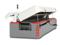
 Encoders can detect distance traveled based on the number of pulses counted. In most applications, rotary motion is converted to linear travel by mechanical components like pulleys, drive gears and friction wheels. In this illustration of a cutting table, if the diameter of the friction wheel and the PPR of the encoder are known, linear travel can be calculated. Pulse count to achieve desired linear travel can be calculated in a similar fashion to the diagram above for devices that use ball screws, gears or pulleys to convert rotary motion to linear travel.
In the equation, C is the number of encoder pulses counted, L is the desired cut length in inches, D is the friction wheel diameter in inches, and PPR is the total pulses per revolution of the encoder. The second equation is based on a desired cut length of 12″. Assuming the friction wheel diameter is 8″ and encoder PPR is 2000 we can calculate that 955 pulses must be counted to achieve a cut length of 12″.
Quadrature Decoding
 Quadrature decoding is a means of increasing the accuracy of the encoder by counting every state change from both channels in one cycle. Both channel A and channel B produce two state changes (switching between high and low) per square wave cycle. The quadrature decoder circuit (shown on the right) uses logic gates to detect a state change on both the A and B channels and it compares the current state to the previous one. If it senses that the encoder is moving forward, it will send out a pulse on either the Count Up output; and conversely if it senses backwards movement it will send a pulse on the Count Down output. All the user needs to do is keep track of how many pulses occur on which line to know how many increments the encoder has moved.
What is Commutation?

Commutation is the process of applying current to a motor so that a rotating magnetic field may be established. In the illustration, current is commutated to windings in the stator. The stator is on the perimeter of the motor and does not move. The permanent magnets in the rotor are attracted and/or repelled by the magnetic fields in the stator created as a result of precisely timed application of current through the commutation process.
The illustration above is very simple. Notice that poles in the stator are alternately energized with a polarity that magnetically attracts the rotor to move in a clockwise direction. In the real world, both attraction and repulsion are used to increase speed, power and efficiency.
Electric Motor Basics
Motors with brushes and commutator are inexpensive but require a lot more maintenance than brushless motors. The brushes erode and fail, create friction, impede current and decrease efficiency. The advent of motor controllers has driven a strong and steady market shift toward brushless motors. Brushless motors require another method of current commutation. Hall devices are cheap but not very accurate, and are usually used with a position encoder increasing cost and BOM count. Resolvers are very accurate and durable but very expensive. Encoders with commutation output have become dominant because they are very accurate, already required in many cases for position feedback, and the cost is competitive.

There are four typical methods of commutating current in a motor:
- Brushes/mechanical commutator Inefficient, high-maintenance
- Hall device Inexpensive but inaccurate, ±1~3°
- Encoder with commutation output Very accurate and cost competitive
- Resolver Extreme accuracy, extreme expense
Brushed vs Brushless
 Permanent Magnet |
 Brushless DC |
|
| Voltage | DC | AC, DC (Control) |
| Speed | 1,000-5,000 | 1,000-5,000 |
| Horsepower | Medium | High |
| Efficiency | 60%-70% | 65%-80% |
| Life | Medium | Very High |
| Maintainance | Medium | Very High |
| Noise | Medium | Very Quiet |
| Speed Regulation | Fair | Excellent |
| Starting Torque | Very High | Very High |
How Brush Commutators Function
Different from BLDC (brushless dc motors), brush motors use only two connections instead of the three phases that BLDC motors use. In the case of a brush motor, only positive or negative dc voltage is applied. The voltage level, and polarity (positive or negative) dictate speed and direction.
 In Fig. 1 the ends of the armature are mainly repelled by both permanent magnet poles and attracted to the opposite magnet poles they are moving toward.
In Fig. 2 the ends of the armature are equally repelled and attracted by both magnets. If the rotor does not have enough inertia to rotate beyond this point the motor is in danger of locking. For this reason 2 pole motors are not very popular and not often used.
In Fig. 3 the ends of the armature are mainly attracted by both magnets and barely repelled by either magnet. The polarity of the magnets in the rotor will change when the split in the commutator ring passes beyond the brushes. At that point the current will be reversed changing the south pole of the rotor to north, and the north pole of the rotor to south.
Brushless Motor Advantages
 Brushless servomotors, including many stepper motors, have become dominant in the automation market over the last twenty years. Their high efficiency, low maintenance, declining acquisition cost and high reliability have resulted in broad market acceptance and utilization. The AMT31 Series, with its commutation output, has been designed to mate with brushless motors.
- No brushes to wear out – less maintenance
- Speed can be precisely controlled
- Much higher power efficiency
- Rotation can be easily reversed
- The AMT31 Series is made for brushless motors
Encoder Commutation Output
 The UVW channels generate square waves that are configured based on the number of poles in the brushless motor. A motor controller reads the UVW pulses and vectors current to the stator windings accordingly. In order to properly time the incidence of current to the stator windings correctly, the encoder and motor must both begin at the zero point.
Most brushless motors have a feature that locks the rotor in the zero position. Usually the commutation encoder must be aligned manually by sight. This can be a tedious and time-consuming process. The AMT31 Series eliminates this procedure. When the motor rotor is in the zero position, the AMT31 Series is mounted and zero position is instantly established via serial communication using CUI’s AMT Viewpoint™ graphical user interface or the One Touch Zero™ module.
Types of Rotary Encoders
Just as there are many methods of commutating current to a motor, there are many types of encoders that can perform that task.
Optical
 Optical encoders with commutation output currently dominate the market, most often used in precision applications and built in to electronic devices to control motion.
- Generates output code using infrared light and phototransistor
- The most common type of encoder available
- Most often used in precision applications and built in to electronic devices to control motion
Magnetic
 Magnetic encoders with commutation output are often used in applications where there are extreme temperatures, high humidity or exposure to particulates or liquids.
- Generates output code by detecting changes in magnetic flux fields
- Most often used in adverse environments
- Resistant to most airborne contaminants
Fiber Optic
 Fiber optic commutation encoders are sometimes called ‘explosion proof’ and are used in applications where methane, propane, or other highly combustible gases are present.
- Generates output code by using a laser and phototransistor
- Most often used in explosion-proof applications where extremely flammable gasses are present
Capacitive
 The AMT31 is not recommended for explosion-proof applications but can withstand similar environmental factors as magnetic encoders and generally outperform optical encoders thanks to its proprietary capacitive technology.
- Generates output code through detecting changes in capacitance using a high frequency reference signal
- Relatively new compared to the other types listed
- Technology has been used for years in digital calipers and has proven to be highly reliable and accurate
How a Capacitive Encoder Works
 The revolutionary AMT31 Series consists of three basic parts as shown in the image. The ac field transmitter emits a signal that is modulated by the metal pattern on the rotor as it turns. The sinusoidal metal pattern on the rotor creates a signal modulation that is repetitive and predictable. This occurs as a result of varying capacitive reactance between the signal generated by the transmitter and the metal on the rotor. The field receiver uses a proprietary ASIC to convert the modulated signal into output pulses that can be read by the same circuits used to receive optical encoder output.
If you have ever used digital calipers, you are already familiar with capacitive encoding. The code generation used in digital calipers for decades is the same technology built into the AMT. This capacitive code-generation technology has been shown to be reliable, accurate, economical and rugged enough to outlast other types of optical encoders.
Product Benefits
 The AMT encoder platform is unique among modular, commutation encoders because it is able to combine durability, accuracy and efficiency in one solution. Thanks to its capacitive design, the AMT is not susceptible to environmental contaminants such as dirt, dust and oil that would disable a typical optical encoder. Additional advantages include the lack of an LED which can eventually fail, a wider temperature range, higher vibration tolerances, and very low current consumption. The digital nature of the design also allows for increased flexibility through programmability of various features, ultimately reducing assembly time and cost compared to other encoders. And, compared to magnetic encoders typically valued for their rugged performance, the AMT Series offers higher accuracy and stable performance under various temperature conditions.
Rugged
- Not susceptible to enivronmental contaminants
- Higher operating temperature range
- No LEDs to fail
- Far less susceptible to vibration
Cost
- Greatly reduced assembly time & cost
Consumption & Accuracy
- Lower current consumption
- Higher accuracy
Features
The AMT31 Series offers a number of key specifications and features that differentiates it vs. the competition. Mechanically, it is low profile and light-weight. The encoder is rugged, offering a broad temperature range and immunity to dust and particulates. It is green, with a current consumption much lower than optical encoders. It is intelligent, providing on-board diagnostic data for quick analysis during design or in the field. Finally, the AMT31 is flexible, offering a number of mounting options as well as the ability to set a range of resolutions, pole counts, and zero position programmatically via serial communication through CUI’s AMT Viewpoint™ graphical user interface.
- 11 mm depth, 15g net weight (0.53 oz.)
- -40 to +125°C operating temperature range
- <10 mA current consumption
- Available diagnostic data for quick analysis in the field or during design
- Program resolution, pole count, zero position
- 9 interchangable common shaft diameters
Ideal for Direct Motor Mounting
 With 4 mounting options and 9 shaft bushings the AMT31 Series encoder can easily mount to almost any brushless motor. Its low mass disc means virtually no additional backlash or increased moment of inertia making it a more reliable component for measuring and controlling the motor. Its small size allows for mounting in tight spaces and to small motors.
Zero position is easily set by CUI’s AMT Viewpoint GUI or by the AMT One Touch Zero Module accessory. Installing a commutation optical encoder onto a brushless dc motor can be an iterative and time consuming process. The optical disk must be physically and precisely rotated to align with the correct motor windings. Once aligned, the assembly must then be checked via back EMF to ensure mounting accuracy. This process can take upwards of 15 minutes per motor. The AMT, being ASIC and MCU based, reduces this time consuming process to a few seconds via the “One Touch Zero” feature, saving time and cost during the manufacturing process.
- 9 shaft diameter options
- Extremely low mass reduces potential backlash
- Small size fits in tight spaces
- Quick and easy mounting process
- Zero position set by AMT Viewpoint GUI or AMT OTZ Module – no mechanical adjustment!
Product Assembly and Mounting
With the disk built-in to the top cover, assembly is very quick and easy. Just snap the shaft adapter over a selected sleeve on the back shaft of a BLDC motor, align and mount the selected base unit with one of the mounting hole options, and snap the top cover into place in seconds. The top cover of the AMT31 houses the circuitry that detects the motor shaft rotation. These top covers are metal, adding durability.
- Assembly of the AMT31 Series requires minimal time and effort
- With just a few durable pieces, it snaps together in seconds without risk of damaging a glass optical disk or other fragile components

Versatile Shaft and Mounting Options
The AMT31 Series kits come with 9 color-coded sleeves that will adapt to 9 different motor shaft diameters. Typical commutation encoders on the market today fit only one motor size per sku. For example, if a manufacturer is utilizing motors with 2 mm, 5 mm and 8 mm shafts in their system, they must purchase three separate encoders. With four popular mounting patterns and nine shaft size options, the AMT31 Series kit can fit all three applications under one sku. With the ability to adapt to almost any application, the AMT31 is the most flexible commutation encoder on the market today.
Mounting Patterns
| Hole Pattern mm/in |
Number of Holes | Hole Size |
| Ø16/0.63 | 2 | M1.6 |
| Ø19.05/0.75 | 2 | #4 |
| Ø21.45/0.844 | 3 | M1.6 or M2 |
| Ø25.4/1.0 | 4 | M1.6 or M2 |
Shaft Adapter & Sleeves

AMT Viewpoint
 Thanks to the AMTs innovative design, CUI is able to deliver an unprecedented level of visibility and control through the AMT Viewpoint™ Graphical User Interface. Via the simple to use software, users are able to set and control a range of parameters, including resolution, zero position, and pole count, reducing development time and virtually eliminating tedious steps in the assembly process. Additionally, the software allows engineers access to a range of diagnostic data for quick analysis during design or in the field.
With the AMT Viewpoint™ GUI you can:
Configure
- Resolution
- Direction of rotation
- Zero position
- Pole count
View
- Resolution/pole count/direction settings
- Output waveform
- Encoder firmware and date code
- Commutation logic values
- Encoder diagnostics
Available Products
The AMT31 Series generates standard U/V/W commutation signals for vectoring current to brushless motors. The encoder can be programmed to commutate 2, 4, 6, 8, 10, 12, or 20 pole motors. While 2048 PPR is the default resolution, 20 resolutions ranging from 48 to 4096 PPR can be programmed by the user. For environments with significant electrical noise or when the distance between the encoder and the receiving circuit exceeds 30 feet, line driver outputs are available for quadrature outputs, commutation outputs, or both. And, depending on the required orientation, customers can select between radial and axial mounting versions of the AMT31.
Commutation Encoder
- U, V, W commutation lines
- Programmable pole # selection: 2, 4, 6, 8, 10, 12, 20
- Programmable incremental outputs
- Optional line driver output
- Radial (AMT312) and axial (AMT313) mounting options
AMT31-V Kit Description
 The AMT31 Series kit comes with an encoder preset to 2048 ppr, a shaft adaptor, 9 sleeve options ranging from 2 mm to 8 mm, two simple mounting tools, and base plates with multiple pre-drilled mounting hole patterns to mate with a wide range of motors. Available AMT31 options include radial or axial encoder orientations, and CMOS voltage or line driver outputs. For quick access to the zero set function in the production environment, CUI offers a One Touch Zero module to help the user set the zero position in seconds.
AMT31-V kit includes:
- AMT31 Series encoder
- Shaft adaptor and 9 sleeves
- Standard and wide bases
- Centering tool
- Spacing tool
Available options:
- Radial or axial orientations
- CMOS voltage or line driver output
Available accessories:
-
- One Touch Zero Module (AMT-OTZ-1)

Summary
In summary, the AMT31 series delivers the best of both worlds, combining levels of accuracy and durability unrivaled in other encoder technologies. The AMT’s unique platform also delivers an unparalleled level of flexibility and intelligence thanks to the digital nature of the design. And, the encoders are easy to install, greatly reducing assembly time and cost.